I love, love, love Saturn by [Rain2], which comes in two versions. The first, which is notably more complex, is shown here with its rings-of-Saturn thumb clusters.
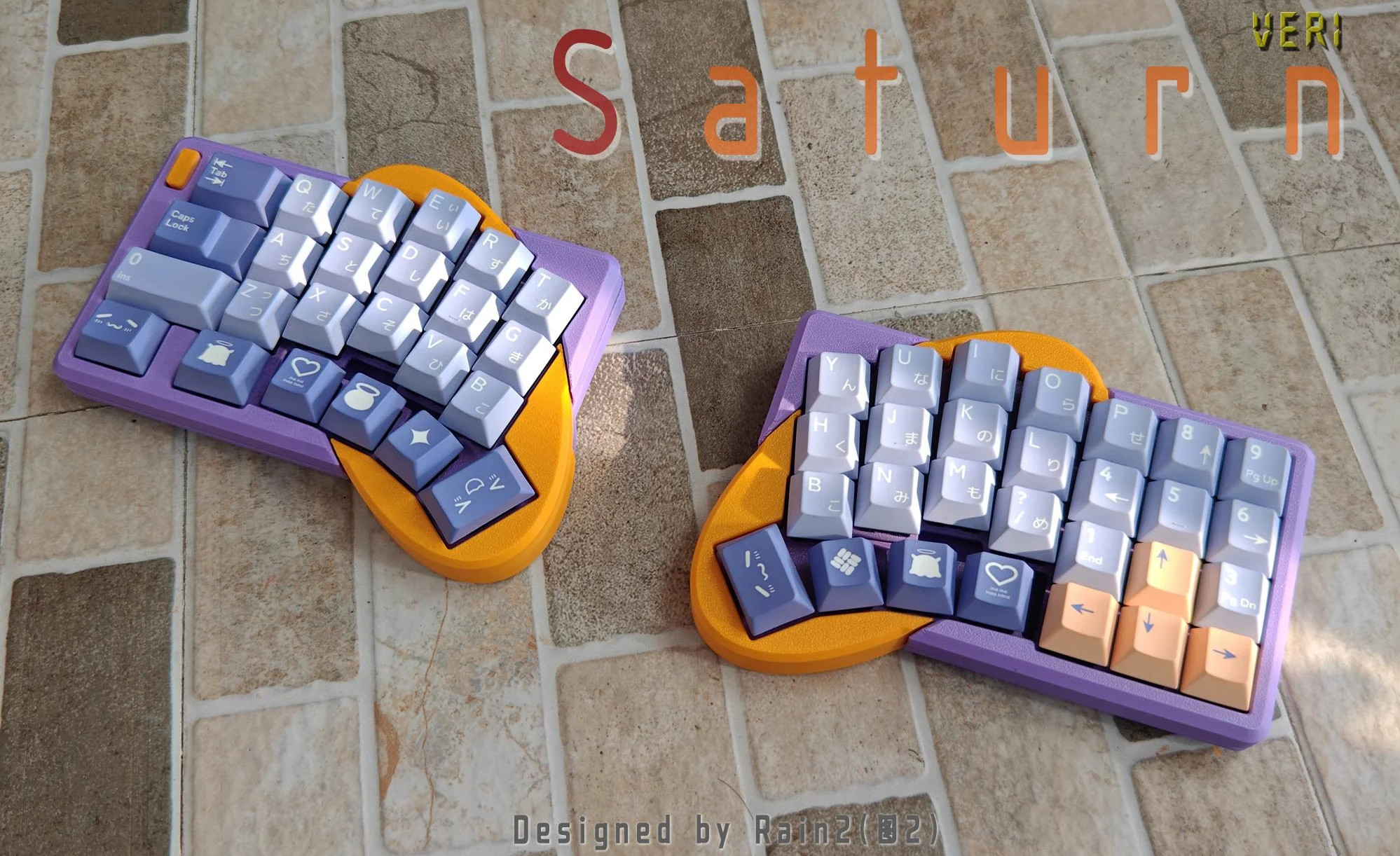
Saturn has one built right in. The basic idea was to add a num pad while keeping the total number of keys to a minimum. Thanks to a mod key, this area can be many things, including but not limited to a num pad.
As far as the far-out shape goes, and I love that the curvature covers the thumb cluster and the index finger, [Rain2] wanted to get away from the traditional thumb cluster design. Be sure to check out the back of the boards in the image gallery.
Unfortunately, this version is too complicated to make, so v2 does not have the cool collision shapes going for it. But it is still an excellent keyboard, and perhaps will be open source someday.
Phanny Kicks Butt
Say hello to Phanny, a custom 52-key wireless split from [SfBattleBeagle]. This interestingly-named board has a custom splay that they designed from the ground up along with PCBWay, who sponsored the PCBs in the first place.
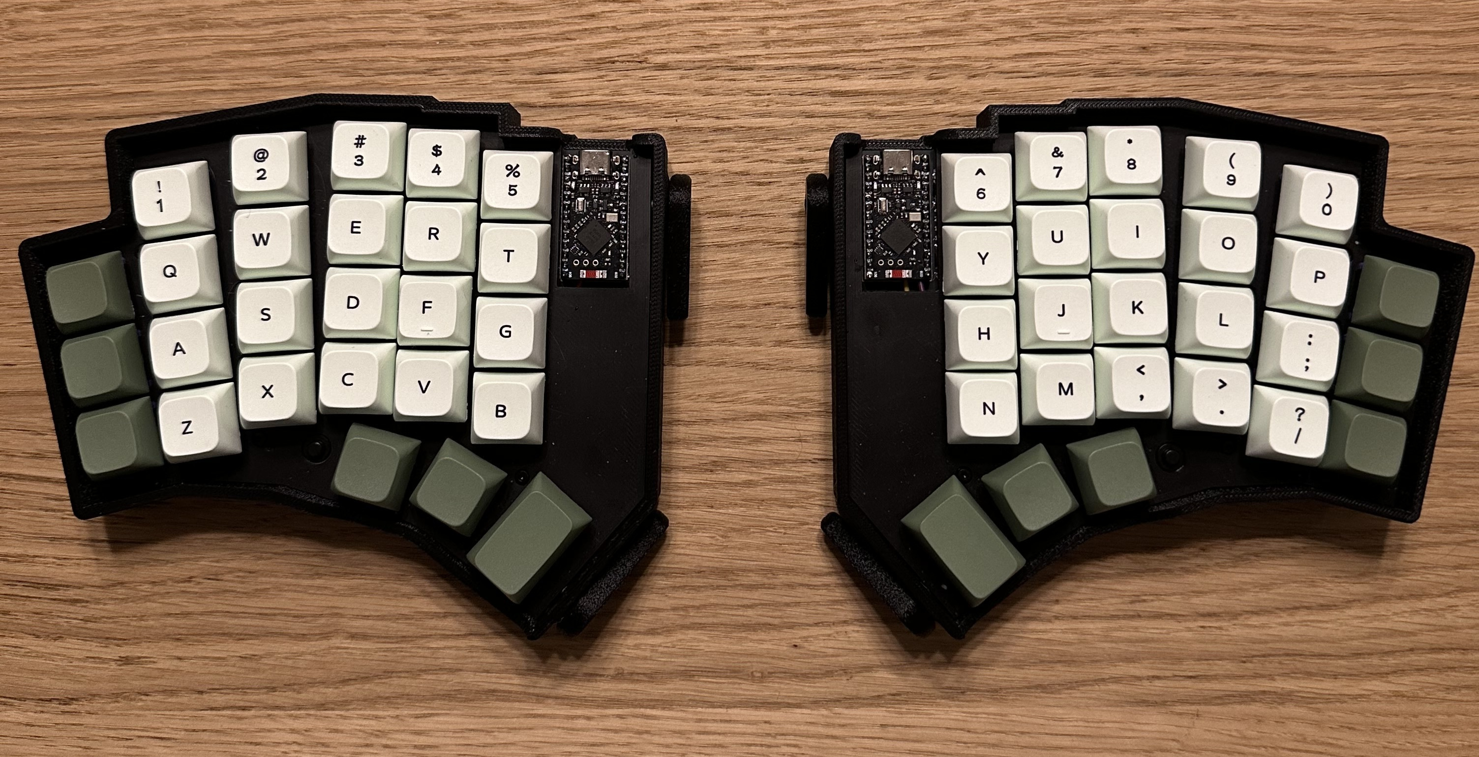
While Ergogen is all the rage, [SfBattleBeagle] still opts to use Fusion and KiCad, preferring the UI of the average CAD program. If you’re wondering about the lack of palm rests, the main reason is that [SfBattleBeagle] tends to bounce between screens, as well as moving between the split and the num pad. To that end, they are currently designing a pair of sliding wrist skates that I would love to hear more about.
Be sure to check out the GitHub repo for all the details and a nice build guide. [SfBattleBeagle] says this is a fun project and results in a very comfy board.
The Centerfold: Mantis WIP is Captivating
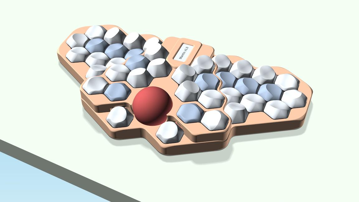
Via reddit
Do you rock a sweet set of peripherals on a screamin’ desk pad? Send me a picture along with your handle and all the gory details, and you could be featured here!
Historical Clackers: the Masspro
I must say, the Antikey Chop doesn’t have much to say about the Masspro typewriter, and for good reason.
But here’s what we know: the Masspro was invented by a George Francis Rose, who was the son of Frank S. Rose, inventor of the Standard Folding Typewriter. That machine was the predecessor to the Corona No. 3.
Frank died right as the Rose Typewriter Co. was starting to get somewhere. George took over, but then it needed financing pretty badly.
Angel investor and congressman Bill Conger took over the company, relocated, and renamed it the Standard Folding Typewriter Co. According to the Antikey Chop, “selling his father’s company was arguably George’s greatest contribution to typewriter history”.
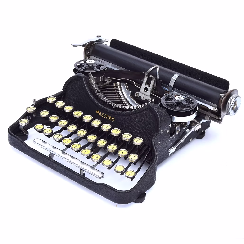
George Rose was an engineer like his father, but he was not very original when it came to typewriters. The Masspro is familiar yet foreign, and resembles the Corona Four. Although the patent was issued in 1925, production didn’t begin until 1932, and likely ended within to years.
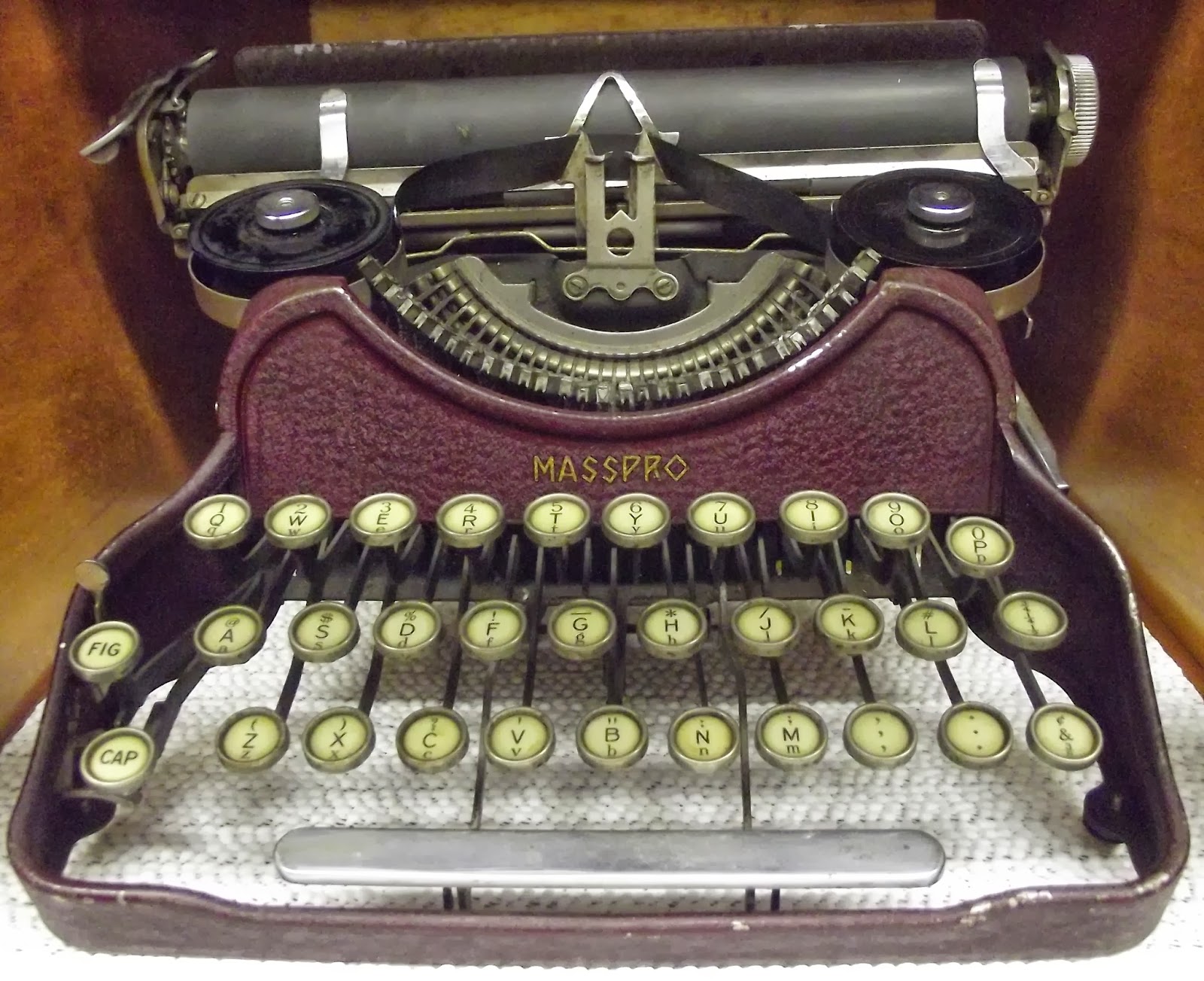
Why? It was the wrong machine at the wrong time. Plus, it was poorly built, and bore a double-shift keyboard which was outdated by this time. And, oh yeah, the company was started during the Depression.
But I like the Masspro. I think my favorite part, aside from the open keyboard, is the logo, which looks either like hieroglyphics or letters chiseled into a stone tablet.
I also like the textured firewall area where the logo is stamped. The Antikey Chop calls this a crinkle finish. Apparently, they came in black, blue, green, and red. The red isn’t candy apple, it’s more of an ox-blood red, and that’s just fine with me. I’d love to see the blue and green, though. Oh, here’s the green.
Finally, a Trackball Mouse With Nice Switches
Okay, so Keychron’s new Nape Pro mouse is pretty darn cool, and this is the best picture I could find that actually shows how you’re supposed to implement this thing on your desk. Otherwise, it looks like some kind of presentation remote.
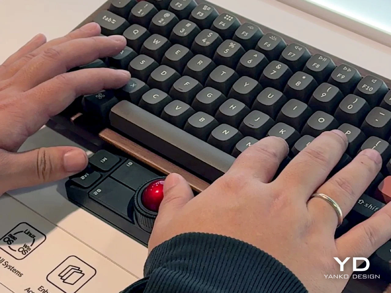
So the idea here is to never take your hands off the keyboard to mouse, although you can use it off to the side like a regular trackball if you want. I say the ability to leave your fingers on the home row is even better.
There are plenty of keyboards with trackpads and other mousing functions that let you do this. But maybe you’re not ready to go that far. This mouse is a nice, easy first step.
The ball is pretty small at 25 mm. For comparison, the M575 uses a 34 mm ball, which is pretty common for trackball mice. Under those six buttons are quiet Huano micro switches, which makes sense, but I personally think loud-ish mice are nice enough.
I’ve never given it much thought, but the switches on my Logitech M575 are nice and clicky. I wonder how these compare, but I don’t see a sound sample. If the Nape Pro switches sound anything like this, then wowsers, that is quiet.
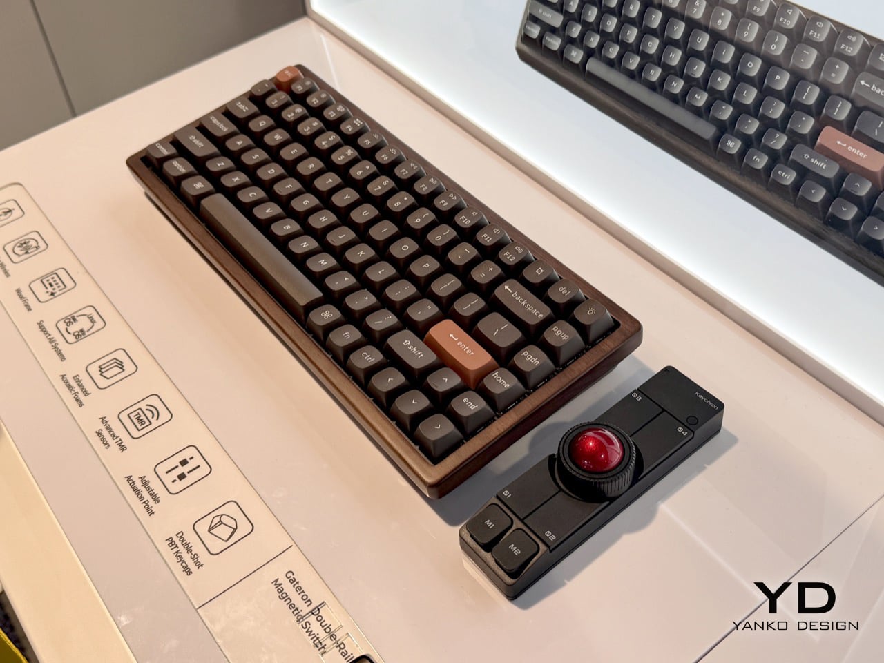
The super-cool part here is the software and orientation system, which they call OctaShift. The thing knows how it’s positioned and can remap its functions to match. M1 and M2 are meant to be your primary mouse buttons, and they are reported to be comfortable to reach in any position.
Inside you’ll find a Realtek chip with a 1 kHz polling rate along with a PixArt PAW3222 sensor, which puts this mouse in the realm of decent wireless gaming mice. But the connectivity choice is yours between dongle, Bluetooth, and USB-C cable.
And check this out: the firmware is ZMK, and Keychron plans to release the case STLs. Finally, it seems the mouse world is catching up with the keyboard world a bit.
Got a hot tip that has like, anything to do with keyboards? Help me out by sending in a link or two. Don’t want all the Hackaday scribes to see it? Feel free to email me directly.


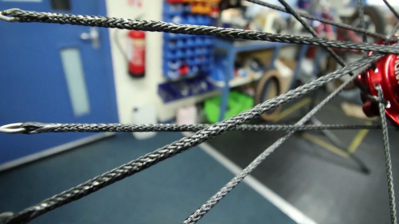
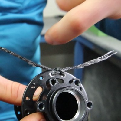 As detailed by [Ali Clarkson], one method involves creating loops out of bike spokes, with a custom jig and some brazing. Then a length of rope is passed through the hub and a special hitch is used to keep it in place. Two loops are made in the ends of this length of rope and passed through the spoke ends made earlier. Finally everything is brought up to tension and trued much like a normal wheelset. The front wheel ended up weighing around 700g, a rather impressive feat for a 24 inch downhill wheel.