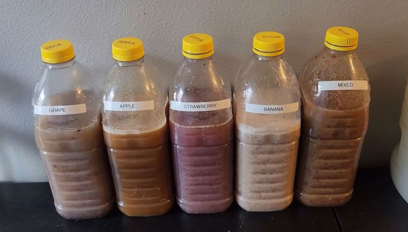
Mysterious Files PH

Tuesday, February 3, 2026

Rewinding a Car Alternator for 240 Volt

February 03, 2026 0
Two phases installed on the stator. (Credit: FarmCraft101, YouTube)

As part of his quest to find the best affordable generator for his DIY hydroelectric power system, [FarmCraft101] is trying out a range of off-the-shelf and DIY solutions, with in his most recent video trying his hands at the very relaxing activity of rewiring the stator of an alternator.

Normally car alternators output 12VDC after internal rectification, but due to the hundreds of meters from the turbine to the shed, he’d like a higher voltage to curb transmission losses. The easiest way to get a higher voltage out of a car alternator is to change up the wiring on the stator, which is definitely one of those highly educational tasks.

Disassembling an alternator is easy enough, but removing the copper windings from the stator is quite an ordeal, as they were not designed to ever move even a fraction of a millimeter after assembly.

With that arduous task finished, the rewinding was done using 22 AWG copper enamel wire, compared to the original 16 AWG wire, and increasing the loops per coil from 8 to 30. This rewinding isn’t too complicated if you know what you’re doing, with each coil on each of the three windings placed in an alternating fashion, matching the alternating South/North poles on the rotor.

Each phase’s winding is offset by two slots, leaving space for the other two phases, which then correspondingly are 90° out of phase when running, creating the three-phase AC output. This is further detailed in the video.

To make sure the windings do not short out on the stator, each slot has a bit of Nomex insulating paper placed into it, and a PETG 3D printed slot holder makes sure that none of the windings sneak out of their slot after installation.

The phases were connected in a Wye configuration, which gives it the maximum possible voltage rather than optimizing it for current as in a Delta configuration.

With the rewinding done, the alternator was reassembled, and the three-phase output of the new stator tested. After some trial and error it was able to do 200 VDC after passing it through an external rectifier, for a total of 700 Watt.

While not an unmitigated success, it seems quite possible to use this alternator as a higher-voltage generator with the hydro setup, especially after the upcoming replacement of the rotor’s electromagnet with neodymium magnets to further simplify it. As a bonus, if he ever needs to rebuild a broken alternator from scratch, rewinding a stator is now child’s play.


Ysgrifennu Côd yn Gymraeg (Writing Code in Welsh)

February 03, 2026 0
Ysgrifennu Côd yn Gymraeg (Writing Code in Welsh)

Part of traveling the world as an Anglophone involves the uncomfortable realization that everyone else is better at learning your language than people like you are at learning theirs. It’s particularly obvious in the world of programming languages, where English-derived language and syntax rules the roost.

It’s always IF foo THEN bar, and  never SI foo ALORS bar. It is now possible to do something akin to OS foo YNA bar though, because [Richard Hainsworth] has created y Ddraig (the Dragon), a programming language using Welsh language as syntax. (The Welsh double D, “Dd” is pronounced something like an English soft “th” as in “their”)

Under the hood it’s not an entirely new language, instead it’s a Welsh localisation of the Raku language. A localisation file is created, that can as we understand it handle bidirectional transcription between languages. The write-up goes into detail about the process.

There will inevitably be people asking what the point of a programming language for a spoken language with under a million native speakers is, so it’s worth taking a look at that head on. It’s important for Welsh education and the Welsh tech sector because a a geeky kid in a Welsh-medium school Pwllheli deserves to code just as much as an English kid in a school near Oxford, but it goes far beyond Welsh alone. There are many languages and cultures across the world where English is not widely spoken, and every single one of them has those kids like us who pick up a computer and run with it. The more of them that can learn to code, and thrive without having the extra burden of knowing English, the better. Perhaps in a couple of decades we’ll be using code from people who learned this way, without our ever knowing it.

As your scribe, this needs to be added: Mae’n ddrwg gyda fi ffrendiau Cymraeg, mae Cymraeg i yn wael iawn. Dwi’n dôd o’r Rhydychen, ni Pwllheli.


Header image: Jeff Buck, CC BY-SA 2.0.


The Surprising Hackability Of A Knock-Off Chinese Toy Camera

February 03, 2026 0
The Surprising Hackability Of A Knock-Off Chinese Toy Camera

My colleague Lewin on the other side of the world has recently bought himself a new camera. It’s a very cute little thing, a Kodak Charmera, the latest badge-engineered device to carry the venerable photography company’s name. It’s a keyring camera, not much bigger than my thumb, and packing a few-megapixel sensor and a little fixed-focus camera module. They’re all the rage and thus always sold out, so when I saw something similar on AliExpress for just under a tenner I was curious enough to drop in an order. How bad could it be?

A Blatant-Knock-Off With Interesting Internals

My G6 Thumb Camera arrived a few days later, as straightforward a copy of a branded product as I have seen, and while it’s by any measure not a high quality camera, I am pleasantly surprised how bad it isn’t. I’ve received a three megapixel camera with image and movie quality that’s far better than that of the kids toy cameras I’ve played with before at a similar price, and that’s something I find amazing. This isn’t a review of a cheap camera, instead it’s an investigation of what goes into a camera like this one. How can they make a camera that’s almost useful, for under a tenner?

If I were setting out to make this camera, I would reach for a microcontroller and one of the variety of cheap all-in-one camera modules on the market. You can buy just that for a similar price, the so-called ESP32-cam module, which pairs the Tensilica version of the microcontroller with a parallel-interface camera module. You can do all manner of hacks with an ESP32-cam and I have too, but unlike my knock-off Kodak it’s not quite fast enough for usable video. Plus, it doesn’t come with a battery and screen.

The little thumb camera is easy enough to crack open, and doing so reveals a small PCB with as expected a camera module dangling from it on a flexible PCB. It’s got a lens with an M8 mount which technically makes it an interchangeable lens camera, but we doubt anyone’s going to change lenses on this thing. Undoing a couple of screws, the board comes out along with the battery, speaker, and display connection, and on the reverse is the SoC, and a Flash memory chip. It’s an HX-Tech HX3302B, a dedicated IC for small cameras which appears in so many of these devices, but one which is sadly one of those Chinese chips for which almost no info can be found online. Oddly some of the best info comes from a familiar source, Sprite_TM has done a little hacking here and discovered that it has an openRISC 1000 core and the firmware is usually accessible, but beyond that no handy data sheets are to be had.

Just Good Enough To Be A Camera-As-A-Module

A 3D printed Super 8 cartridge inside a movie camera. On the right is a green Raspberry Pi Zero module, while in the foreground is an M12 lens camera module focusing on the film gate towards the back of the scene.
The focal plane focusing technique in action, in my digital Super 8 cartridge.

My camera then can be software-hacked, but not easily. If that were all then we’d be at the end of it, and I’d have merely another trinket. But there’s another reason I bought this thing, and that’s because I wanted a hardware hackable camera, not a software one. I want to use a small sensor like this behind all manner of custom lenses and mirrors in projects featuring repurposed 1970s snapshot cameras, and while I can and have used Raspberry Pi cameras and those ESP32s to do the job, that introduces annoying things like software and power systems to the equation. This camera has the germ of a digital camera as a module; I can take away the M8 lens and surround to replace it with my own optics, and in an instant I have a digital camera of my own without the hassle. Suddenly a just-good-enough novelty camera becomes rather interesting.

So my knock-off novelty integrates a package I would struggle to replicate for the price, and holds the promise of many creative camera hacks to come. I’ll probably follow the path I have with Pi cameras of fitting an M12 macro lens, and rear-focusing on the focal plane of a full-frame film camera for retro digital fun.

In the ten days or so since the work for this article started, the G6 Thumb Camera has been removed from AliExpress in Europe. You can still find it by switching your country to somewhere far-flung, but given that as you can see from the photos above it really is a blatant knock-off of the Kodak product it is hardly surprising that some lawyers have probably made a call. The good news is though that for hacking it doesn’t matter what the case says. I’ll be looking out for the inevitable follow-up, a thumb camera that’s not such a knock-off but which packs the same internals, and if you’re enjoying camera hacking, I suggest you do too.


The Graph Theory of Circuit Sculptures

February 03, 2026 0
The Graph Theory of Circuit Sculptures
A cuboctahedron (a kind of polyhedron) made out of LED filaments is being held above a man's hand in front a computer screen.

Like many of us, [Tim]’s seen online videos of circuit sculptures containing illuminated LED filaments. Unlike most of us, however, he went a step further by using graph theory to design glowing structures made entirely of filaments.

The problem isn’t as straightforward as it might first appear: all the segments need to be illuminated, there should be as few powered junctions as possible, and to allow a single power supply voltage, all paths between powered junctions should have the same length. Ideally, all filaments would carry the same amount of current, but even if they don’t, the difference in brightness isn’t always noticeable. [Tim] found three ways to power these structures: direct current between fixed points, current supplied between alternating points so as to take different paths through the structure, and alternating current supplied between two fixed points (essentially, a glowing full-bridge rectifier).

To find workable structures, [Tim] represented circuits as directed graphs, with each junction being a vertex and each filament a directed edge, then developed filter criteria to find graphs corresponding to working circuits. In the case of power supplied from fixed points, the problem turned out to be equivalent to the edge-geodesic cover problem. Graphs that solve this problem are bipartite, which provided an effective filter criterion. The solutions this method found often had uneven brightness, so he also screened for circuits that could be decomposed into a set of paths that visit each edge exactly once – ensuring that each filament would receive the same current. He also found a set of conditions to identify circuits using rectifier-type alternating current driving, which you can see on the webpage he created to visualize the different possible structures.

We’ve seen some artistic illuminated circuit art before, some using LED filaments. This project doesn’t take exactly the same approach, but if you’re interested in more about graph theory and route planning, check out this article.


Monday, February 2, 2026

A Higher-End Pico-Based Oscilloscope

February 02, 2026 0
A Higher-End Pico-Based Oscilloscope
A set of three stacked oscilloscopes is shown. The lower two oscilloscopes have screens and input pins visible, and the top oscilloscope is reversed, with a printed back plate visible.

Hackers have been building their own basic oscilloscopes out of inexpensive MCUs and cheap LCD screens for some years now, but microcontrollers have recently become fast enough to actually make such ‘scopes useful. [NJJ], for example, used a pair of Raspberry Pi Picos to build Picotronix, an extensible combined oscilloscope and logic analyzer.

This isn’t an open-source project, but it is quite well-documented, and the general design logic and workings of the device are freely available. The main board holds two Picos, one for data sampling and one to handle control, display, and external communication. The control unit is made out of stacked PCBs surrounded by a 3D-printed housing; the pinout diagrams printed on the back panel are a helpful touch. One interesting technique was to use a trimmed length of clear 3D printer filament as a light pipe for an indicator LED.

Even the protocol used to communicate between the Picos is documented; the datagrams are rather reminiscent of Ethernet frames, and can originate either from one of the Picos or from a host computer. This lets the control board operate as an automatic testing station reporting data over a wireless or USB-connected network. The display module is therefore optional hardware, and a variety of other boards (called picoPods) can be connected to the Picotronix control board. These include a faster ADC, adapters for various analog input spans, a differential analog input probe, a 12-bit logic state analyzer, and a DAC for signal generation.

If this project inspired you to make your own, we’ve also seen other Pico-based oscilloscopes before, including one that used a phone for the display.


Usagi’s New Computer is a Gas!

February 02, 2026 0

[Dave] over at Usagi Electric has a mystery on his hands in the form of a computer. He picked up a Motorola 68000 based machine at a local swap meet.  A few boards, a backplane, and a power supply. The only information provided is the machines original purpose: gas station pump control.

The computer in question is an embedded system. It uses a VME backplane, and all the cards are of the 3u variaety. The 68k and associated support chips are on one card.  Memory is on another.  A third card contains four serial ports. The software lives across three different EPROM chips. Time for a bit of reverse engineering!

[Dave] quickly dumped the ROMs and looked for strings. Since the 68k is a big endian machine, some byte swapping was required to get things human readable. Once byte swapped, huge tables of human readable strings revealed themselves, including an OS version. The computer runs pSOS, an older 68k based real time operating system – exactly what one would expect a machine from the 80’s to run.

The next step was to give it some power and see if the gas station computer would pump once again.  The LEDs lit up, and a repeating signal showed up from one of the serial ports. The serial connections on this machine are RS-485.  Not common for home computers, but used quite a bit in industrial embedded systems.  Unfortunately, the machine wouldn’t respond to commands sent from a terminal. The communication protocol remained a mystery.

Since this video has gone up though, several people have provided a wealth of information at the vintage-micros channel over on [Dave’s] Usagi Electric Discord.

Gas pumps are a bit of a departure from [Dave’s] usual minicomputer work. We’re no strangers to embedded systems here though.


Teardown of an Apple AirTag 2 With Die Shots

February 02, 2026 0

There are a few possible ways to do a teardown of new electronics like the Apple AirTag 2 tracker, with [electronupdate] opting to go down to the silicon level, with die shots of the major ICs in a recent teardown video. Some high-resolution photos are also found on the separate blog page.

First we get to see the outside of the device, followed by the individual layers of the sandwiched rings of the device, starting with the small speaker, which is surrounded by the antenna for the ultrawide band (UWB) feature.

Next is the PCB layer, with a brief analysis of the main ICs, before they get lifted off and decapped for an intimate look at their insides. These include the Nordic Semiconductor nRF52840 Bluetooth chip, which also runs the firmware of the device.

The big corroded-looking grey rectangle on the PCB is the UWB chip assembly, with the die shot visible in the heading image. It provides the localization feature of the AirTag that allows you to tell where the tag is precisely. In the die analysis we get a basic explanation of what the structures visible are for. Basically it uses an array of antennae that allows the determination of time-of-flight and with it the direction of the requesting device relative to it.

In addition to die shots of the BT and UWB chips we also get the die shot of the Bosch-made accelerometer chip, as well as an SPI memory device, likely an EEPROM of some description.

As for disabling the speaker in these AirTag 2 devices, it’s nestled deep inside, well away from the battery. This is said to make disabling it much harder without a destructive disassembly, yet as iFixit demonstrated, it’s actually fairly easy to do it non-destructively.