Sunday, September 27, 2026

Center-Pivot System Modified to Mow Lawn

September 27, 2026 0

When flying over the United States, Australia, and a few other vast and relatively empty parts of the world, strange circular formations can be spotted. These are typically center-pivot irrigation systems, an effective way to irrigate crops if efficient use of space is not too big of a priority. Keeping these massive machines in a straight line is an interesting engineering problem, though, and [rctestflight] built a miniature version of his that works on the same principle but mows his lawn instead.

These systems work as semi-independent sections that are flexibly coupled at either end. The control scheme initially used here was to drive the outermost set of wheels at a constant speed, and then use limit switches at each coupling inside of that to drive inner sets of wheels once the outer set passes a setpoint. Eventually a potentiometer-based proportional controller was installed in place of the limit switches. With some other drivetrain issues sorted out it was on to building the mower attachment. This uses a pair of pivoting precision knives mounted to motors that ride along a carriage attached to any one of the linkages of the center-pivot system. Limit switches keep the carriage riding back and forth cutting the lawn as it traverses the grass.

With the system in place, [rctestflight] set out to optimize it mostly out of a desire to tinker with a thing that he had built. The challenge for him is that his location in the Pacific Northwest is generally very damp, so in addition to corrosion and other water damage on various parts, there were also issues of mud complicating the way the wheels navigated the terrain, as well as the plant growth being fairly rapid and often impeding the process of the robot as well. One of the perks, though, was that the circular area was already largely carved out thanks to some of his earlier projects testing the durability of RC cars.


Going on a Tangent with the Intel 8087’s Hybrid CORDIC Algorithm

September 27, 2026 0
Going on a Tangent with the Intel 8087’s Hybrid CORDIC Algorithm

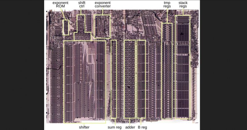
Continuing their reverse-engineering of Intel’s 8087 FPU, [Ken Shirriff] and friends took a look at one of the trigonometric functions, specifically FPTAN.  The most exciting part with such reverse-engineering is probably figuring out which algorithm was used in the implementation, while trying to determine the reasoning behind the final hardware design.

If you’re running a simple MCU or MPU like the 6502 or Z80 without hardware functions you’d likely use an algorithm such as CORDIC or similar, as this requires only basic hardware features like addition, subtraction, bitshift, and look-up tables. One can also use polynomial approximation if there’s hardware support for a potential speed-up, or as is the case in the 8087, create a hybrid approach that targets speed and accuracy.

In the article the exact implementation to get to 64 bits of accuracy is detailed, starting with the 16 bits calculated using CORDIC before switching to the Padé approximant technique involving the ratio of two polynomials. Since after calculating the brunt of the final value with CORDIC the remainder is a fairly small value this polynomial approximation not just very accurate but also fast.

This approach allows the FPTAN and similar trigonometric functions in this FPU to hit a very high level of accuracy and not require the look-up table sizes and additional time required to work through the remaining bits with CORDIC. For those who want to see the full algorithm Intel’s engineers used, [Ken] has the full microcode listing with comments in the article as well.

As for the exact speed-up from this approach, [Ken] calculates for one value that FPTAN would spend 33% on CORDIC pseudo-division, 47% on CORDIC pseudo-multiplication and a mere 15% on the polynomial approximation along with about 5% overhead.

With the Pentium series of CPUs Intel moved completely away from CORDIC, as it’s clear that as accurate as it may be, it’s hard to scale to a significant number of bits without incurring significant time penalties. With the introduction of SIMD instructions the x87 ISA has further seen its functionality reduced, but this analysis shows once again why the 8087 made such an impact when it was released.


Defeating Satellite Spoofing with Galileo’s Encryption

September 27, 2026 0
Defeating Satellite Spoofing with Galileo’s Encryption
A digital map is shown with a series of red waypoints making a roughly C-shaped curve. A smaller group of green waypoints stays stationary near one of the corners of the map.

Considering how important it is for everything from navigation to keeping clocks in sync, satellite navigation systems are surprisingly vulnerable to a variety of attacks, ranging from simple jamming to more sophisticated spoofing attacks. This may be changing, though, as Galileo, Europe’s GNSS, recently demonstrated its first cryptographically-secured position fix under spoofing conditions.

Most GNSS systems, including GPS, have no verification measures to keep an adversary from transmitting a false signal at a higher power and hijacking a receiver; since GNSS signals are extremely weak by the time they reach the ground, this presents no great difficulty to a moderately well-equipped attacker.

Galileo’s Signal Authentication System (SAS) aims to fix this. The Galileo ground station pre-selects signal spreading codes, which it then encrypts with a regularly-changing secret key and publishes. A receiver which anticipates needing a verified signal can then download these encrypted codes ahead of time and store them. Galileo satellites then transmit on the E6-C pilot signal, and the receiver records the signal. After transmitting a message block, it then transmits the decryption key on a separate signal, which the receiver uses to recover the spreading codes. The receiver then correlates these spreading codes with the recorded signal to find the satellite’s pseudorange.

It’s a rather complicated system, but it works: earlier this month in Andøya, Norway, the annual Jammertest GNSS testing event took place. For one week, a wide range of organizations tested the resilience of their GNSS systems against various attacks, including jamming, delayed retransmission, and spoofing. Using five Galileo satellites, the European Space Agency was able to obtain a stable lock on their receiver even during spoofing.

In principle, this method could be extended to other GNSS systems. There’s certainly motivation to do so; very large-scale attacks have been demonstrated recently.


Ways To Empirically Identify a Magnet’s Polarity

September 27, 2026 0

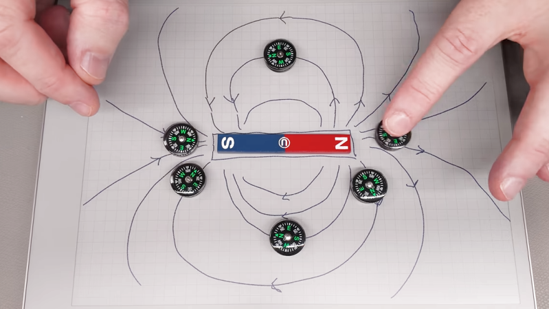
Every magnet has a north and a south pole, but which is which? Sometimes it matters. If a product one builds features a magnetic closure or other part, the polarity of those magnets should be consistent in assembly. So how does one ensure they never glue a magnet wrong again? [Clough42] shows several ways to identify a magnet’s north and south poles using things many of us probably have ready at hand, and goes into a bit of theory while he’s at it.

Probably the easiest way is to use a known-good and clearly labeled reference magnet. Same poles repel, and opposites attract. But if that’s not available, a simple magnetic compass can help. Because opposite poles attract, a compass’s north point will be attracted toward a magnet’s south pole, and vice versa.

A Hall effect sensor, or an electromagnet — the winding and current flow determine the polarity — are other ways to measure a magnet’s poles. And here’s where [Clough42] dives into some details of how magnetic fields actually act, because it explains some seemingly strange behavior.

For example, at around 4:08 he demonstrates a Hall effect sensor board that is documented as lighting an LED when the south pole of a magnet is held to its front. It does that, but it also lights the LED when the north end of the magnet is held to the sensor’s back. That’s because the sensor isn’t actually directly sensing the magnet’s pole, it’s sensing the orientation of a magnetic field. The lesson is clear: make sure you’re measuring what you think you’re measuring. Near the end of the video he demonstrates a similar experience with a handy mobile phone app that senses magnetic fields by reading the device’s internal magnetic compass; by waving a strong magnet around, the detected polarity flips back and forth even though the magnet’s orientation isn’t changed.

So what does one do after positively identifying a magnet’s north and south poles? Label it clearly for use as a known-good reference magnet in the future is our suggestion. Watch the whole video below, then take a few minutes to dive into the nitty-gritty of what magnets actually are and how they work.


Saturday, September 26, 2026

A Modular Macro Keypad

September 26, 2026 0

The introduction of the ATmega32U4 microcontroller, with its integrated USB controller, made a lot of hardware tasks much simpler than they were before. One of the arenas it revolutionized was custom keyboards, making it much easier to build not only standard mechanical keyboards, but keyboards of all kinds of shapes and layouts and custom macro keyboards as well. This trend has continued on for the better part of the past decade with other microcontrollers beyond the 32U4 now available as well, but this modular macro keypad takes it to a new level by keeping that simplicity but also keeping costs down.

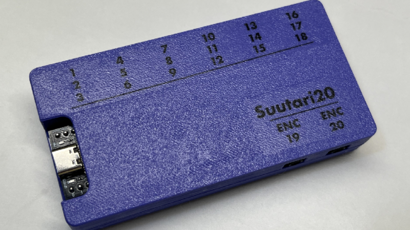
The suutari20, as it is called by its creator [Squalius] is able to achieve these aims by using 3.5 mm jacks commonly found in audio equipment. Each jack can support up to three keys, with the hub ultimately able to support 18 different keys. Those can include analog devices as well, such as volume knobs or jog controllers. The macro pad is powered by an RP2040 microcontroller from a Raspberry Pi Pico and uses QMK firmware, so those already familiar with custom keyboard programming will have no problem getting started.

From there, all that’s needed is a case, in this example a 3D printed one, and the commodity audio hardware to plug everything in to. It enables whatever functions can be thought of in a macro pad, and although the design focuses on simplicity and cost, this macro pad takes the concept to the extreme with modular keys that each have their own microcontroller built-in.


Cheap Yellow Display Dreams of PDA

September 26, 2026 0
Cheap Yellow Display Dreams of PDA
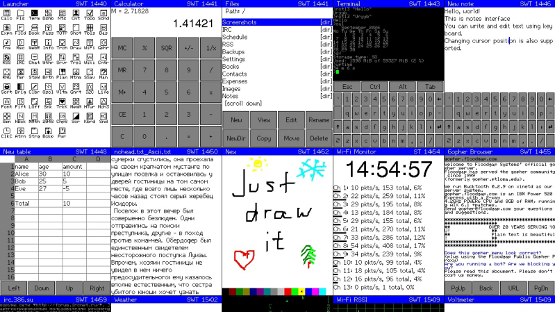
A grid of screenshots of various applications on the CYD PDA

Everybody loves the Cheap Yellow Display (CYD) ESP32 dev boards, so why not treat yours to a little PDA? That’s right: turn it into a Portable Digital Assistant and relive the glory days of Palm with this project from [sau412].

For those readers who are too young to remember, a PDA was basically a phoneless and cameraless smart-phone, and devices running Palm Corporation’s Palm OS ruled the roost for most of the 90s and early 2000s. [sau412] hasn’t written an emulator or port of Palm OS; rather he’s created his own firmware for the ESP32-based CYD that is inspired by the PDAs of yore, and has many features you’d have expected back in the day. That includes a Gopher browser, to let you check out the undying alternative to the World Wide Web. There isn’t a general-purpose web browser, but there are RSS and Wikipedia readers, and what else do you need? At least you won’t end up doomscrolling.

There are also a passel of games and a BASIC interpreter, and the usual practical things like a calendar, calculator and contact list. Everything from ebook readers to translators, all of it by [sau421]. If you’ve got a CYD kicking around, you could do worse than give it a little PDA. Using the web-based flasher, we had it up and running in five minutes or so, but without an SD card we couldn’t test all the apps.

This is hardly the first ESP32 PDA  that we’ve featured, but leaning into the CYD means it’s the simplest project to replicate.  If you’re jonesing for the original Palm OS experience on more modern hardware, Pumpkin OS can get you going on x86 or ARM.


Self-Repairing Conductive Material from Liquid Metal

September 26, 2026 0

PCB circuits are cool, but you know what is cooler? Terminator circuits that’s what! And what if the same material that makes Terminator circuits could also be used for smart heat sinks, flexible circuits, and self-healing material properties? Well, that is exactly what the lab at Virginia Tech’s VT MADE Lab has created, presented by Joel from [3DPrintingNerd].

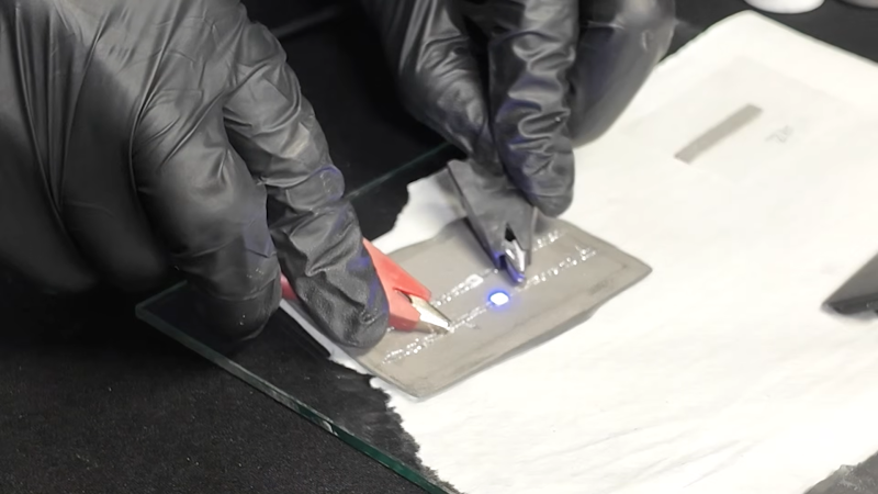
So what does a Terminator circuit actually entail? Well, just like in Terminator 2, the circuits are made of liquid metal. Specifically, small drops of liquid metal alloy made of gallium and indium. These drops are contained within a matrix of PDMS polymer, which contains the magical liquid for conductivity, thermal and electrical . This makes a flexible and stretchy composite which can even self-repair when punctured or cut by bridging the

Little “bubbles” of liquid alloy form a composite that will pop when applied over a threshold of force or puncture.

broken circuit with the liquid alloy. Having a polymer matrix allows this self-repairing property but also makes the material insulating by default, only allowing current to flow after selectively “popping” the matrix bubbles.

To create something with the composite material, you’ll find it similar to many other resin-based materials. You can pour, mold, and even 3d print a custom geometry. A short bake later and you get a solidified model made for whatever custom flexible circuitry you have in mind.

While this process requires chemicals, polymerization reactions, and a taste for liquid alloys, that shouldn’t stop you from trying out flexible electronics. For a more hands on method to flexible electronics check out this glove with circuits running throughout!